This tutorial will explain my workflow when making a normal map for a character. I'll be using 3DSMax though most of it will transfer to any program. As with everything I write, take it with a grain of salt, compare it to what you know, and figure out what you want to use from it for yourself.
First I'm going to explain what a normal map is and does, from an artists perspective. Imagine a styrofoam head that is faceted and chunky. This is like our low poly model. Then imagine coating it in clay and sculpting a much more detailed face on top of it. Then you slit this clay from the back, and pry it off. Lay it flat on the table, and you will see that it is thick in some places, and thin in others where the edges of the chunky head (the low poly model) came close to the surface. This layer of clay is what gives the definition to the sculpture, whereas it was featureless and flat before the clay was added. This is what a normal map does, though it is virtual and doesn't change the actual silhouette. It tells the engine how to display the light hitting the object. Current hardware can only handle a certain number of polygons still, but normal maps give us more detail without actually stressing the processors as much as trying to render the high poly models that the normal map comes from.
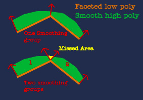
Next I'll explain how the "bake" works. The low poly casts "rays" out from it's surface, using it's smoothing groups to determine the direction the rays are cast. You can enhance and tweak the rays in some programs by using a "cage" which I'll explain further later on. If you apply smoothing groups to a model, it will not only display a razor sharp crease in the model in game, going against the look of the other defined edges in the normal map, but the "bake" will also miss portions of the high poly. This image should help explain.
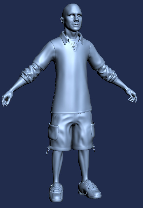
The first thing I do when making an asset that will have a normal map, is to make a "sketch" model. I make this model quickly, trying to hit my target polycount for the in game model. I pay attention to silhouette and meshflow as well. This is so that I can know how much detail my low poly will "hold". If you make a high poly model, without any regard to the polycount you have for the low poly version, you might find that you made it too detailed, with too many things breaking the silhouette, and then you'll have to go and delete portions of your high poly, wasting valuable time. Normal maps work best on large smooth planar surfaces. The rounder and smoother your low poly, the better the normal maps will catch and hold. Whenever you have to make too many quick changes in surface direction, the normal map won't work as well. I try to keep my low poly one solid mesh, with one smoothing group. The reasons I make my meshes watertight, is that when you have intersecting elements, the normals don't average. This means when the normal map displays it won't average either, and you will have a hard intersect. I didn't save that state of this model, so imagine that this model is rougher and doesn't match up with the high poly so well.
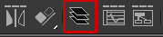
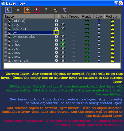
Layers are extremely important when creating normal maps in max. These are the most commonly used buttons for my workflow. I encourage you to learn the other buttons as well, but this should give you a crash course in the layer panel. In order to bring this layer manager up, click this button.
Current layer. Any created object, or merged objects will be on this layer. Check the empty box on another layer to switch to the current layer.
Hidden icon. Click it to turn it to a dash mark and that layer will become visible. Click the dash to turn it to the eye symbol and it will become hidden.
New layer button. Click this to create a new layer. Any currently selected objects will be added to this newly created layer.
Add selected object to current layer button. With an object selected, highlight a layer, then click this button and the boejct will be added to the highlighted layer.
Select content button. When you click this button, all objects on the current selected layer will be selected.
I keep my sketch model on a layer called "low". I make a new layer named after whatever part I'm working on. In this case it was "body" and I merged in a body I'd made before and started altering it to fit this project. I'm not going to cover high poly asset creation here, I'm going to assume you've made your high poly in your package of choice, be it zbrush, XSI, Modo, or others, and merged it back into max. Try to keep all your chunks as organized as possible on different layers. This is especially important if you don't have a great video card, as you can speed up your viewport manipulation by only having one layer visible at a time.
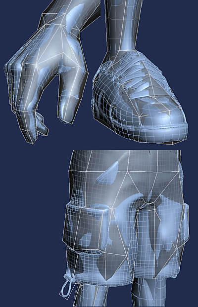
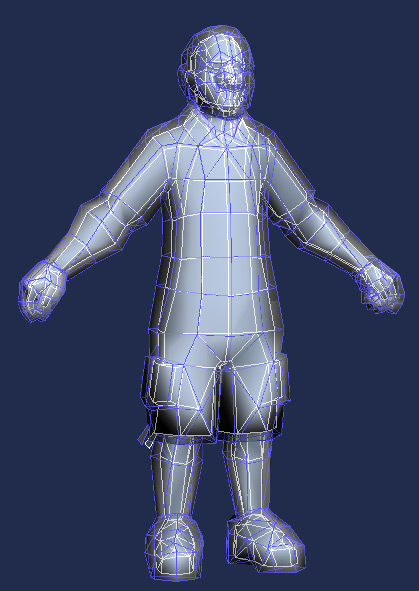
Now comes time to tighten up your sketch model to match up with the high poly. I like to put the low poly on X-ray mode (alt+x) so I can see the high poly inside it. To speed up your view, only show wireframe on selected object, as displaying the wireframe on your high poly slows the scene down a lot. To do this, right click perspective in the upper right corner of your viewport and go to Configure at the bottom. Then in the Rendering Method tab, tick the display selected with edged faces button. This way when you have edged faces turned off, whatever you select still gets edged faces. Try to match the surface of your low poly as closely as possible to the high poly. The goal is to capture the silhouette and volume of the high poly. Pay particular attention to parts that break the silhouette. There is a script on Scriptspot called "Tim's Scripts" that has a conform macroscript in it. If you have a solid mesh as your high poly, you can use this script to pop the verticies of your low poly to the surface of your high poly.
After you have matched your low poly to the high poly, it's time to layout UV's. When making UV layouts for use with normal maps, there are a couple things to be mindful of. The first is what your target engine is capable of. Also, keep in mind that UV chunks can be facing "forward" or "backwards". The way to tell, is to apply a texture with some text on it. If the text displays correctly, it's facing forwards. If the text displays in reverse, it's backwards. Whenever you use the Planar map function in the Unwrap UVW editor, with it set to average normals, it will map them facing "forwards" Likewise if you use the UVhelp script (www.microcan.nl) when you relax something, it will relax them so that they face forwards. There are generally three types of engines:
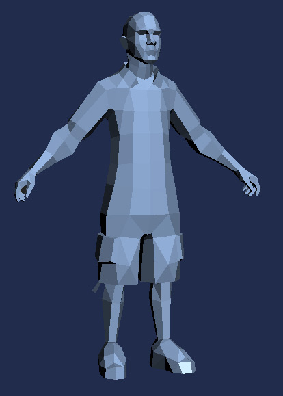
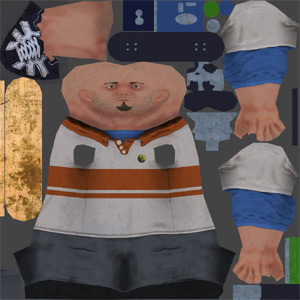
Regardless of your engine type, there are some rules to making good UV layouts. The first is to have as few seams as possible. No matter what the engine, seams always seem to show up. Hide your seams in non visible areas. Be twice as anal about hiding seams as you would be on a color map only model. Try to keep things as relaxed as possible so that if you apply a checker map, the squares all appear uniform and straight. Use the UVhelp script till max 8 comes out (max 8 has a working relax function) UVhelp and documentation can be had from www.microcan.nl Whenever possible have seams lie on the same axis, either horizontal or vertical. The best example I can give is a cylinder. Don't let it curve in the UV layout, straighten it so that each seams is parallel to each other. If your engine type is number 1 or 2, this is twice as important. This is because of the way that a normal map is stored in RGB. In the below example, I created this model as if I had access to engine type 2 (which is how max displays things). The arms are mapped so that the seam is parallel to itself on either side. Same with the head seams. The head is welded to the torso and the pants, to eliminate as many seams as possible.
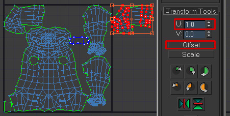
If you are using 3DSMax as your baker (baking normal maps is only available in max 7 and up) you may not have any UV chunks overlapping. Grab the offending chunks (in the above example, both legs and feet grabbed from the same chunk). Then using Unwrap tools (available at www.chuggnut.com and YES it does work in max 7 despite him claiming it only works for 5) offset those chunks a value of 1.0 in either U or V direction (I prefer U). What this does, is moves it out of the way so that the max bake doesn't error (it ignores chunks outside of the UV square) but when a texture is applied, because the texture tiles, those chunks still get the exact texture area that their in-the-square counterparts get. This is why it's so important to offset it exactly 1.0 and nothing more or less. If you were to leave the chunks overlapping, your render would have a wireframe overlay of reversed normals, and in the color map, you'd have sparkly colors or a wireframe overlay.
After your UV's are finalized be sure to reset Xforms on your low poly. Make sure your Smoothing groups are set up correctly (I put all of mine on SG 1) Now press the zero key to bring up the Render to Texture dialog box. Alternatively you can get to it under the render menu.
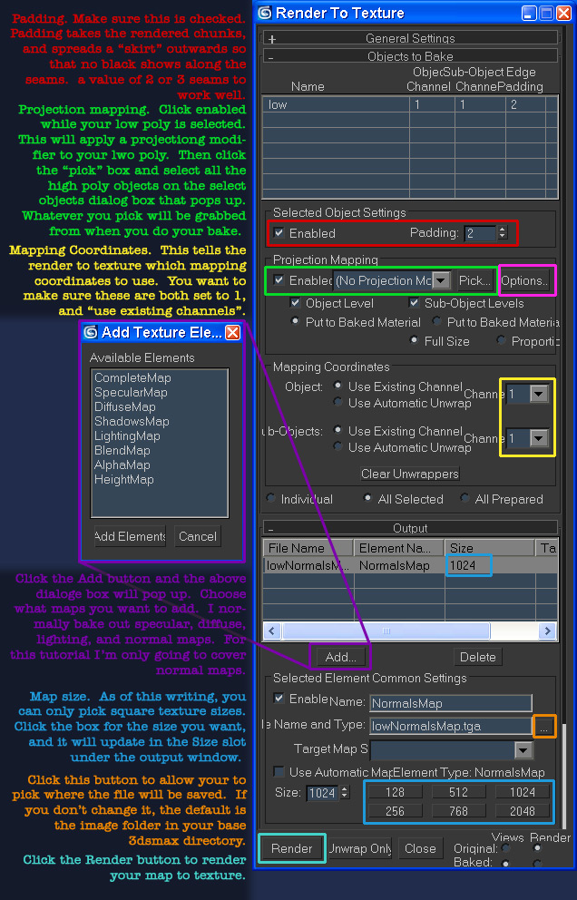
Padding. Make sure this is checked. Padding takes the rendered chunks and spreads a "skirt" outwards so that no black shows along the seams. A value of 2 or 3 seems to work well.
Projection mapping. Click enabled while your low poly is selected. This will apply a projection modifier to your low poly. Then click the "pick" and select all the high poly objects on the select object dialog box that pops up. Whatever you pick will be visible to your bake.
Mapping coordinates. This tells the render to texture which mapping coordinates to use. You want to make sure these are both set to one and use "existing channels".
Click the add button and highlighted dialog will pop up. Choose what maps you want to add. I normally bake out specular, diffused, lighting and normal maps. For this tutorial I am only going to cover normal maps.
Map size. Click the box for the sizes you want and it will update in the size slot under the output window.
Map size. Click the box for the sizes you want and it will update in the size slot under the output window.
Click the ... button next to File Name and Type to allow you to pick where the file will be saved. If you don't change it, the default is the image folder in your base 3DSMax directory.
Click the Render button to render your map to texture.
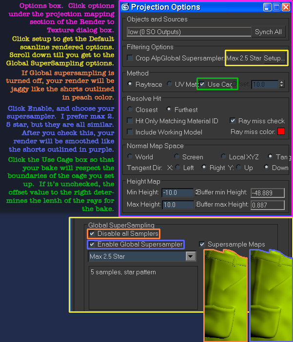
Above outlined in pink is the options box. clicking it brings up the below dialog box.
Options box. Click options under the project mapping section of the Render to Texture dialog box.
Default scanline. Click setup to get the Default scanline render options. Scroll down till you get to the Global Supersampling options.
Global supersampling. If Globa supersampling is turned off, your render will be jaggy like the shorts outlined in peach color.
Enable. Click enable and choose your supersampler. I prefer max 2.5 star, but they are all similar. After your check this, your render will be smoothed like the shorts outlined in purple.
Use Cage. Click the Use Cage box so that your bake will respect the boundaries of the cage you set up. If it's unchecked, the offset value to the right determines the length of the rays for the bake.
Don't render yet. You still need to set up your cage. A cage is very powerful. Without a cage, all the rays cast in the bake will travel the same distance. This will almost always result in it grabbing from areas you don't want it to. The cage lets you not only vary the length, but also the direction the rays are cast. This is very powerful. I always set up a cage for my objects.
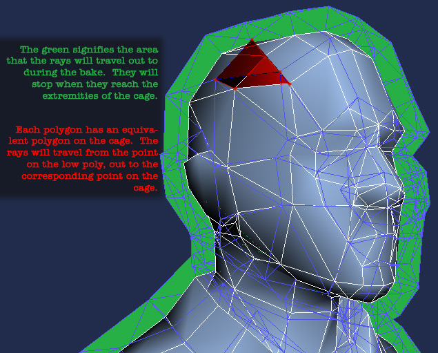
The green signifies the area that the rays will travel out to during the bake. They will stop when they reach the extremities of the cage.
Each polygon has an equivalent polygon on the cage. The rays will travel from the point on the low poly, out to the corresponding point on the cage.
When you bring up the render to texture dialog box, and add the high poly pieces, it automatically applies a projection modifier to your low poly. You can also add this manually using the modifier list.
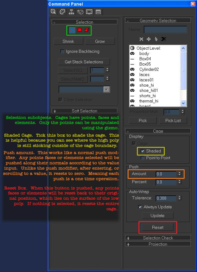
Selection subjects. Cages have points, faces and elements. Only the points can be manipulated using the gizmo.
Shaded Cage. Tick this box to shade the cage. This is helpful because you can see where the high poly is still sticking outside of the cage boundaries.
Push amount. This works like a normal push modifier. Any points faces or elements selected will be pushed along their normals according to the value input. Unlike the push modifier, after entering, or scrolling to a value, it resets to zero meaning each push is a one time operation.
Reset Box. When this button is pushed, any points faces or elements will be reset back to their original position which lies on the surface of the low poly. If nothing is selected, it resets the entire cage.
The first thing I end up having to do to my cage is reset it. It tries to auto fit it, but it has never worked so far. I reset the cage, then I put a push on the entire cage till it encompasses the entire model.
After putting on a universal push, I go into the point sub object selection, and grab the problem areas, then I reset them.

Then I do a smaller push on them so that it's more appropriate for those areas. You will only be able to do certain areas using the push. Some areas are just too problematic, and will need custom tweaking. Go into point mode, and using the move rotate and scale gizmos, tweak the cage to encompass the high poly model without overlapping areas you don't want to pull from.
Remember how I said that the cage can control the direction the rays are cast? Here is how that's immensely beneficial.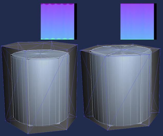
With the unedited cage, the high poly is grabbed unevenly. Where the low poly surface is closer to the high poly, it grabs the edge, but as it gets further away from the hig poly surface, it grabs the top of the high poly first, because of the angle the cage is facing. If you go in and manually edit the cage, so that it is as close to the high poly surface as it can be while still encompassing it, you will get a smooth normal map rendered. This works well on gun barrels, shorts, shirt sleeves, anything that is round, but you don't have enough polys to make it as round as the high poly is. I edited the cage on my skater, so that it would grab from the shorts like the cylinder above on the right. this gave me a nice smooth edge for the shorts normals.
Once your cage is set up, you can render using the render button in the render to texture dialog box.
Once you've rendered out your normal map successfully from max, which might take a few tries till you get your cage set up well, you will have to clean it up. I didn't remember to save one of the early renders of this normal map, but this one still has some errors in it.
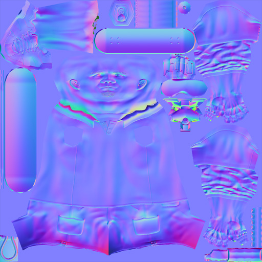
See the collar of the shirt? How it wobbles back and forth? That's something that needs cleaning up. Also the headphone strap at the bottom right is a bit wobbly. This normal map started out with several holes in it also, where the cage wasn't quite large enough, but it wasn't worth rerendering it, so I cleaned them up in photoshop.
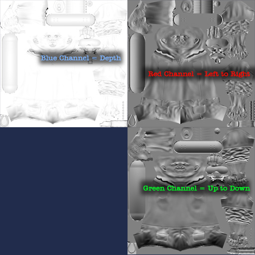
Rather than painting in RGB, which will not only create weird smoothing errors, and hurts your brain, break it down into channels. If you are used to keeping an imaginary light source in your head for traditional texturing, this should be fairly easy to work with. When you want to use the smudge brush per channel, be sure to tick the option box at the top that says "use all layers" or it will not work.
Channels Tab. Click the channels tab to view your channel.
Current channel. Click the tickbox to select which channel you will be painting on.
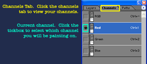
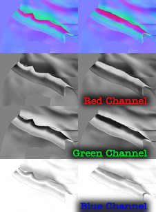
Blue Channel = Depth
Red Channel = Left to Right
Green Channel = Up Down
Here is an example of an area I cleaned up. See how easy it is to understand the changes I made when you approach it per channel? The result is much cleaner than had I tried to fix it in the RGB all at once. Fix all the chunky areas like these, before moving on to adding detail with the NVfilter
After you have cleaned up your Normal map by painting out the errors and holes in each channel, it's time to use the NVfilter to add smaller details. The general rule I use, is if anything is less than an 1/8th inch thick, it should be left to this stage to create. Small details like these don't really benefit from being modeled, and would take much too long to model in high poly, if it's even possible to model them at all. Cloth seams, surface texture, grit, pocks, dings, rust, skin pores, and scratches can all be made very easily using the NVfilter. Which can be had here.
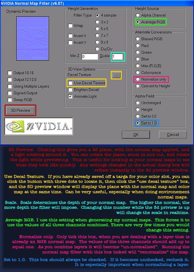
3D Preview. Clicking this gives you a 3D plane with the normal map applied and a light rotating around it. You can rotate the plane, zoom in and our and rotate the light while previewing. This is useful for looking at your normal maps to see what they look like quickly. Any settings changed in the actual dialog box will reflect instantly in the 3D preview winodow.
Use Decal Texture. If you have already saved off a targa for your color slot, you can click the button with three dots to locate it then click the "use decal texture" box and the 3D preview window will display the plane with the normal map and color map at the same time. Can be very useful, especially when doing environment notmal maps.
Scale. Scale determines the depth of your normal map. The higher the normal, the more depth the filter will impose. Changing this number while the 3D preview is up will change the scale in realtime.
Average RGB. I use this setting when generating my normal maps. This forces it to use the values of all three channels combined. There are very few tunes you would change this setting.
Normalize Only. Only click this box when you are dealing with a layer that is already an RGB normal map. The values of the three channels should add up to one. As you combine layers ut will become "un-normalized". Running the normal map filter with this box ticked will "renormalize" the map (making the numbers add up to 1).
Set to 1.0. This box should always be checked. If it becomes unchecked, recheck it. It is especially important when normalizing a layer.
When you prepare a layer to use the filter on, you make it like a traditional bump map. Meaning that the lighter a pixel is, the higher off the surface it will be in the normal map. The blacker it is, the more indented it will seem. Middle grey will appear to lie directly on the surface of the normal map.
I normally prepare my details in layers according to groups. I will do the threads on a shoe in one, and the grit for a tshirt on another. That way I can run the filter on a different scale per layer as is appropriate for the detail in question.
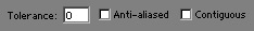
After running the filter, it's good to remove the neutral 128.128.255 purple by using the magic wand set to 0 tollerance and the contiguous box unticked. Click on the large expanse of purple to select it all, and hit the delete key to remove it.
After you have done the above steps, you are ready to combine the filtered layer, with the baked layer. The first step is to select the blue channel only by going into the channels tabs, and then hit ctrl+l to bring up the levels control. Then reduce the blue channels value from 255 to 127. Then put the entire layer on overlay mode. I have an action you can load that does this all in one step called "normal fix".
Channels tab. Click this to get access to the individual channels.
Blue Channel. Click to activate the blue channel only.
Output Levels. Changing these numbers clam the highest and lowest values.
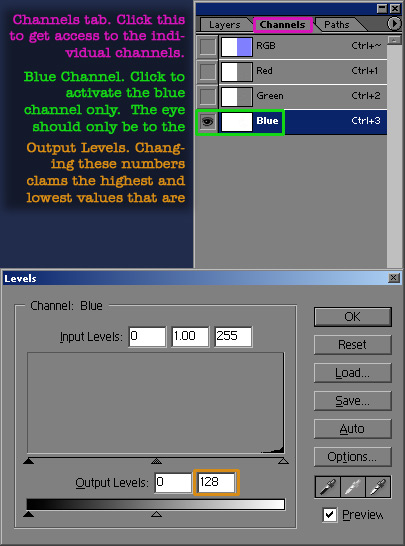
The blue channel from your baked layer, has depth information in it. It's already fairly bleached out, but it's accurate. The blue channel from your nvfiltered version contains almost no value in it. If you didn't half the blue channel from it, it would blow the blue channel out from your baked layer. By halfing the value, when you put it on overlay, it only modulates the blue channel, rather than blowing it out.
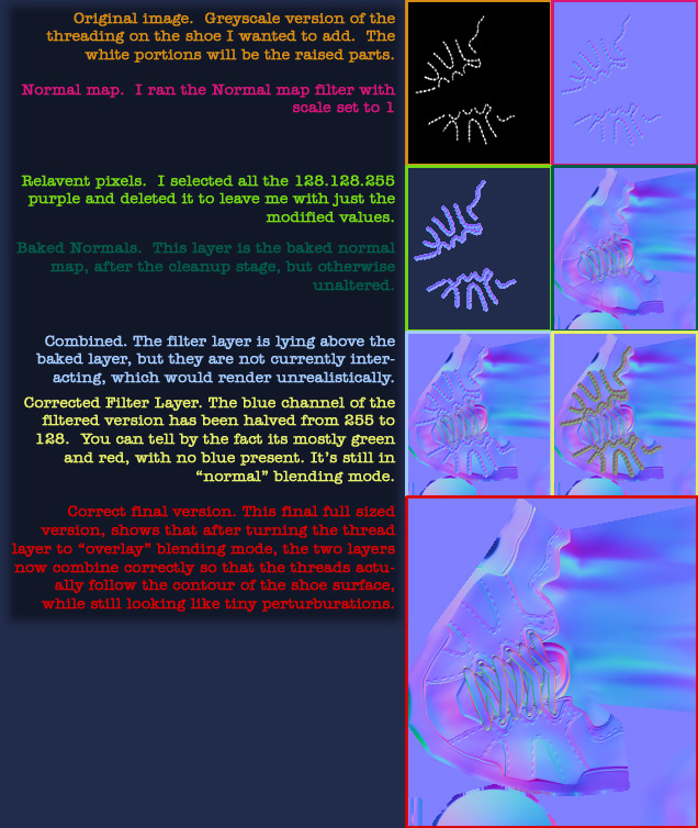
Original image. Greyscale version of the threading on the shoe I wanted to add. The white portions will be raised parts.
Normal map. I ran the normal map filter with scale set to 1.
Relevant pixels. I selected all the 128.128.244 purple and deleted it to leave me with just the modified values.
Baked Normals. This layer is the baked normal map, after the clean up stage, but otherwise unaltered.
Combined. The filter layer is lying above the baked layer but they are not currently interacting which would render unrealistically.
Corrected Filter Layer. The blue channel of the filtered version has been halved from 255 to 128. You can tell by the fact that it is mostly green and red with no blue present. It's still in "normal" blending mode.
Corrected final version. This final full size version shows that after turning the thread layer to "overlay" blending mode the two layers nor combine correctly so that the thread actually follows the contour of the shoe surface while still looking like tiny perturbations.
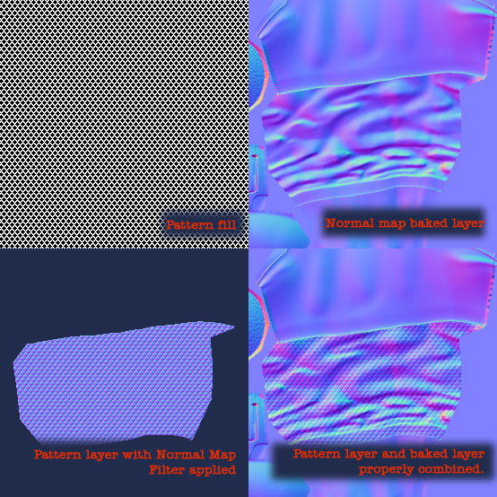
After putting in all the fine details using the Normal Map filter on hand painted layers, you can add even more detail by giving certain materials a different grit than others. The baked versions tend to all be very smooth, which reads well in game, but having some with a rougher "tooth" or a small pattern to diffuse the light can help add realism and varying material types. I like to use photoshops pattern tools for this effect. I have a small library of tileable images that I can use at any point in time. The best part about the pattern function, is that because it works on small tileable images, you can use it on any texture reguardless of size. Sometimes I do have to have two versions of a pattern, one for very small textures, and another for larger textures, so that the detail is still the appropriate size.
Below is an example of a small tileable black and white image. I use the pencil tool to make sure it's very crisp, so that it will read well in the final texture. Define it as a pattern first, then use the fill tool on a blank layer above your baked normal map layer.

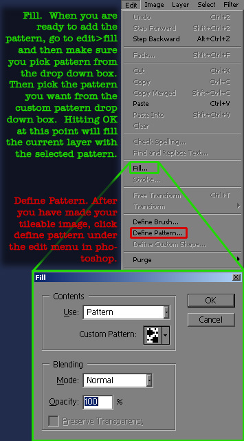
Fill. When you are ready to add the pattern go to Edit > Fill and then make sure you pick Pattern from the drop down box. Then pick the pattern you want from the custom pattern drop down box. Hitting OK at this point will fill the current layer with the selected pattern.
Define Pattern. After you have made your tileable image, click define pattern under the edit menu in Photoshop.
When you are ready to apply a surface pattern to your materials, first create a mask for them, so it will be easy to constrain the pattern to only the area you want it. After you've filled only those areas, follow the steps used above for the shoe detail to combine the pattern and the baked layer.
Overlaying details in photoshop can greatly aid your normal map creation process. It's faster than modeling all of it into the high poly in many cases, and sometimes let's you add details you would have no way of adding otherwise. Add as many layers as you want, but be sure to make a flattened version at the end and run the normal map filter with the "normalize only" setting so that it's all mathematically correct for your engine.
While I'm not going to cover color or specular map creation in this tutorial, I am going to show you how to preview the normal map in 3DSMax 7. It helps to have a color and spec map for preview purposes so I'm going to use ones I've already created.
Color
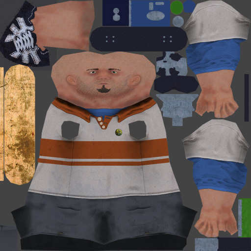
Specular
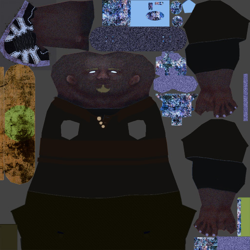
Normal

Next you have to create the material to display your shader in 3DSMAX viewport. This works with max 7 and greater. I'm showing how to use 3DSMAX default shader to keep things simple, and because eventually I'm assuming they will fix their shader in subsequent releases. The main problem is that it only shows maps at 512 or smaller until you render (when it uses the actual map size) and it doesn't handle mirrored bits well (read that as it doesn't handle them at all). But it's a good previewer that works out of the box, and will probably get better with time.
Diffuse color. Put your color map here.
Specular Level and Specular Color. Put your specular map in both of these if it's RGB.
Bump. When you click on the map slot, choose "normal bump" instead of bitmap from the dialog that pops up. Put your normal map in the normal slot in the next window. Also up the amount to 100 from the default 30.
DX display and Show map in viewport. Click the DX display tickbox after you have given the material your maps. Then go to the top and tick the "Show map in viewport" button
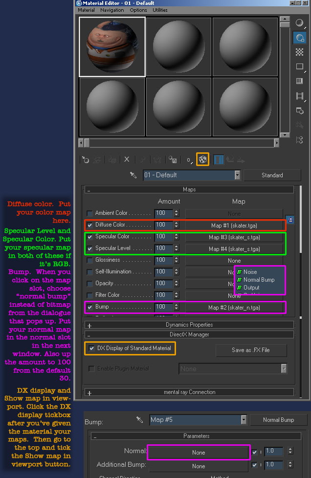
Apply your shader to your low poly and you should now see your model with normal maps. Add as many lights as you like, and they will light the normal map in real time. Use the actual renderer if you want to see maps larger than 512 at actual size.