To change your viewport camera with a shortcut: “f” is the front view, “b” is the bottom view, “l” is left view, “t” is top view, “u” is user view (without perspective), and “p” is perspective. In addition to these defaults, I have “ctrl+b” as back view, and “ctrl+r” as the right view. Holding down “v” will give you the option to choose any view. To focus your view on what is currently selected, hit “z”. It will work on the contents of the scen if you have nothing selected, or just the object if you are in object mode, or show end results is turned on. If you are in sub-object mode, hitting “z” will focus only on the currently selected sub-objects. Changing the camera view and quickly pressing “z” is a good practice so you don’t lose your place. Customizing short cuts is a way to give you faster access to frequently used commands.
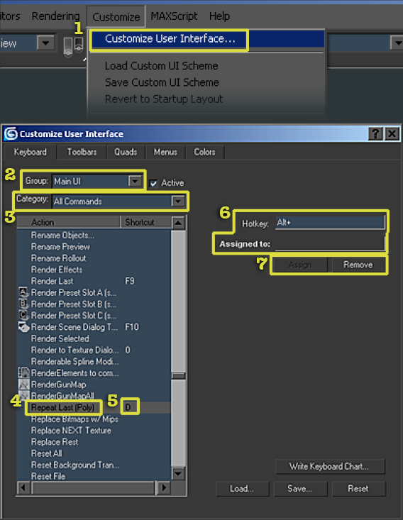
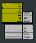
Found under the Customize menu, this gives you access to the customize user interface control box where you can assign short cuts, customize the toolbars, quads, menus, and color.
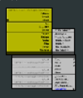
Thee group drop down list contains all the main areas of max’s tools. Pick the section the command you want will be under. When in doubt, pick Main UI.
This drop down list is used to isolate portions of the above Group listing. If left to All Commands, it will list the group in it’s entirety. If you know what area the command is under but not it’s name, isolate it by changing to that Category first.
These are the commands you can assign shortcuts to. If you have a question about a certain Action, you can look up it’s name in the help file.
This column shows the currently assigned shortcut key.
After highlighting an Action, type the key you wish to assign in the Hotkey box. If that key is already assigned to another shortcut, that shortcut will appear in the Assigned to box. is helps to avoid assigning an existing key to a new Action, but it can be overwritten if desired.
Assign will make the key combination in the Hotkey box the new Shortcut. If the Action already has a command, Remove will take it away.
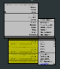
Theere are several important viewport commands for changing the way your model is displayed. The light grey menus are from right clicking on the viewport name in the upper left corner of your viewport. The dark grey are from right clicking on the object and selecting the properties menu.
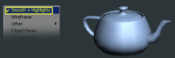
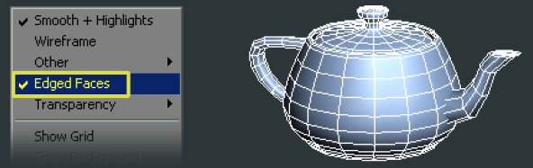
Smooth + Highlights Tapping F3 twice will return you to this option from any alternate viewing mode you might be on.
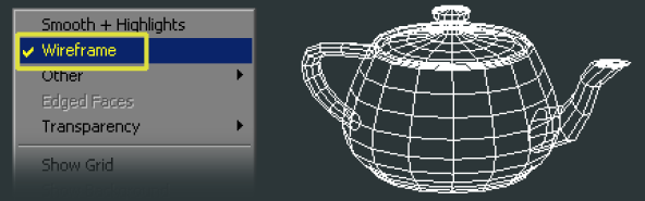
Wireframe Tap F3 to show the object in wireframe only.
Edge Faces Tap F4 to toggle the display of the wireframe over the object.
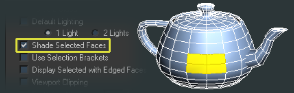
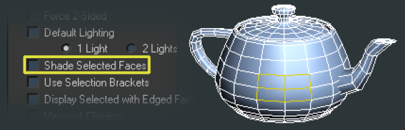
Shade Selected Faces Tap F2 to toggle this mode. When on, faces will display shaded with your selection color (mine has been changed from the default red to the bright yellow-orange in the screen shots). When off, faces will have only a highlighted wireframe around them. Useful when you are in See-through mode and don’t want your face selection obscuring your ortho plane.
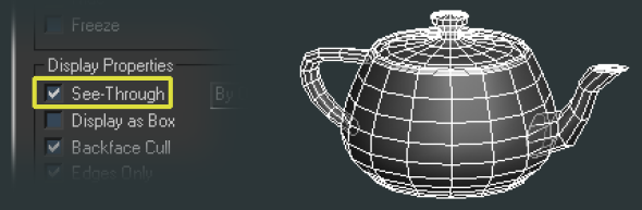
See-Through Press alt+x to enable See-through mode. It makes the object semi transparent, so that you can still see the surface but also through to any underlying objects. To obtain true transparency, apply a shader with 100% opacity.
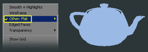
Flat I have assigned F5 to flat mode. Flat shows the scene with no lighting or shading. Useful for previewing textures at full bright, or for examining the silhouette without the internal details distracting you.
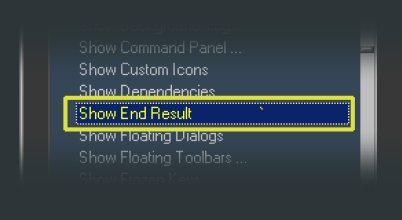
One Short cut I use frequently is Show End Result. It can be accessed by the button below the modifier stack window, but I assign it to the key right below the "Esc" key on the far left top side, for easy access (on the English keyboard it produces the "'" character). It works as a toggle, showing the final results with all modifiers turned on, and then off.
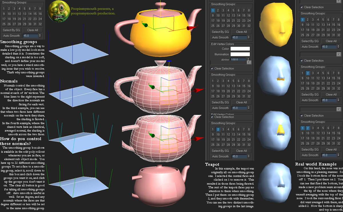
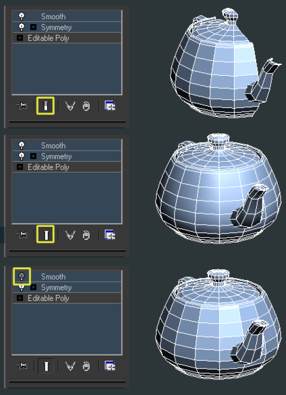
When working with a low poly model, I normally have two modifiers throughout the entire process, Symmetry and Smooth. More information about Symmetry can be found in the Max help file. Smooth is a modifier for adding smoothing groups. I have smoothing group one selected so that the entire object smooths.
I also have downloaded a script from OrionFlame (www.scriptspot.com) called cleanallSGs. It removes all smoothing groups from an object. I have this in my right click menu for easy access, as some operations can add smoothing groups to a model.
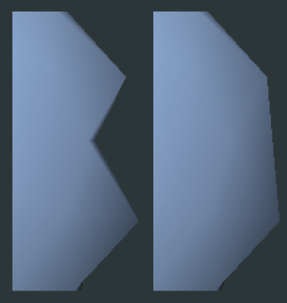
In the screenshots look carefully at the Show End Results button and the lightbulbs next to the modifiers (which turns their effect on and off). In the first one, Show End Results is off, and I see only half of my model. I tap the shortcut key for Show End Results, and the model not only gets a second half, it’s also welded (so that the smoothing groups continue across the seam) and smooths across the entire model. is is how I normally work for the majority of the modeling stage. I like the faceted view to really see the surface of the model and how the faces and edges turn based on their neighbors. However when evaluating the model as a whole I like to see it smoothed as it would appear in a game engine. I might eventually add multiple smoothing groups towards the end, but for the majority I keep them all one one.
When working with a high poly model, I use the Turbosmooth modifier instead of smooth.
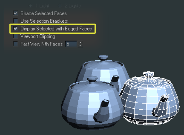
Another useful option, is to right click the viewport name in the upper left corner, and choose configure. In that option box, tick Display Selected with Edged Faces. Now even when you leave wireframe mode by hitting F4, the selected object will show it’s wireframe. I normally use this option when I have on object with several others surrounding or intersecting it. This way I can focus only on the edges of the object I’m working on currently, and not be distracted by the others edges.
Modifier stack navigation. I have the “c” key assigned to “previous modifier”. Any time you click on an object it defaults to the top level of the stack. Pressing “c” repeatedly gets me to the bottom edit poly level. On each modifier, you can access the different sub-object leves with the number keys. In edit poly they are:
Another command to remember, is that you can convert your selection from one to another by holding the “ctrl” key and clicking another subobject button in the right hand window. Make a selection of faces and “ctrl+left mouse button click” the vertex button, and you’ll select the equivalent vertices. If you “ctrl+shift+left mouse button click” you will only get the sub-objects completely covered by the current selection. is works in the UV editor window as well, and the convert commands can be found in the right click quad menu in case you’re using expert mode.
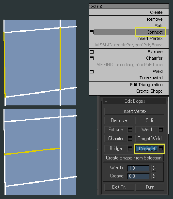
Connect Select two or more edges, or vertices, and you can connect them, as long as they are adjacent to one another. Connecting on edges connects in the middle. You can bring up the option box and choose to connect with more than one edge, all will be evenly spaced.
Connect can be found in the edit poly modifier panel, or by right clicking to get the context sensitive hotbox. It’s in the bottom left portion
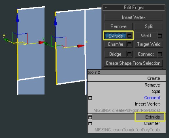
Extruding an edge is easy. Hold the shift key and drag the move gizmo. Release the mouse and drag again to continue extruding a new segment. Can be used on multiple edges as once. Also works with the rotate and scale gizmo.
Extrude can be found in the edit poly modifier panel, or by right clicking to get the context sensitive hotbox. It’s in the bottom left portion.
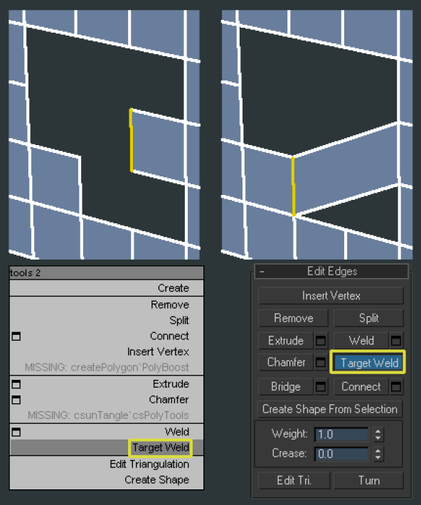
Target weld Works on edges and vertices. Once the tool is activated, you can either click+hold and drag, or click once on the edge/vert you want to move, and then move the cursor to the edge/vert you want to weld to and release, or click again. Target welding edges is normally faster than target welding vertices one at a time. Unless you want to weld a single vert, it’s normally more efficient to target weld in edge mode. I normally click+hold and drag to where I want to weld as it’s fewer steps for the same result.
Click the target weld button, either in the edit poly modifier panel, or in the lower left quadrant of the right click context sensitive menu.
Cut tool Selecting the cut tool lets you draw a line of new edges on your object. Start by clicking anywhere, and then click each time you want a new vertex and change of direction.
Cut is found in the edit poly modifier panel, or the upper left tool box in the right click menu. When finished, right click to exit the too
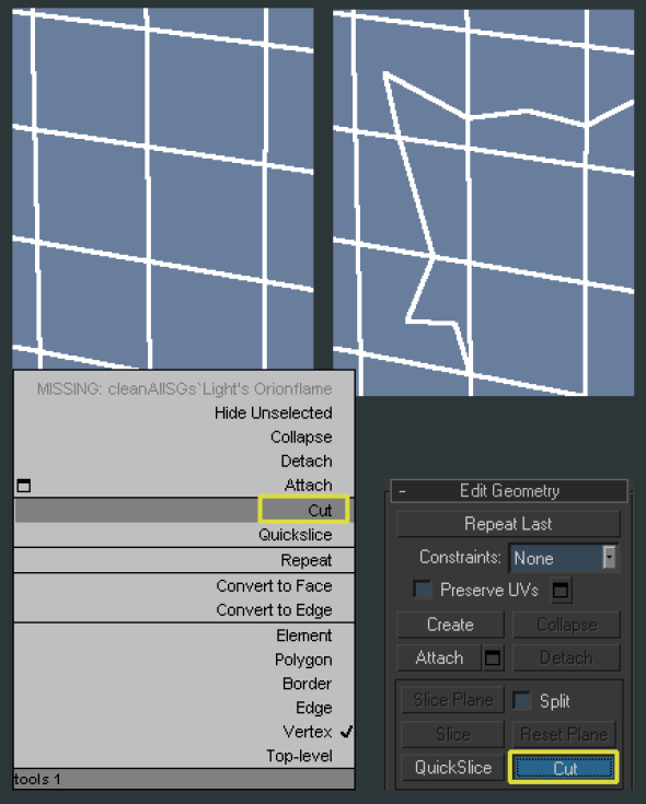
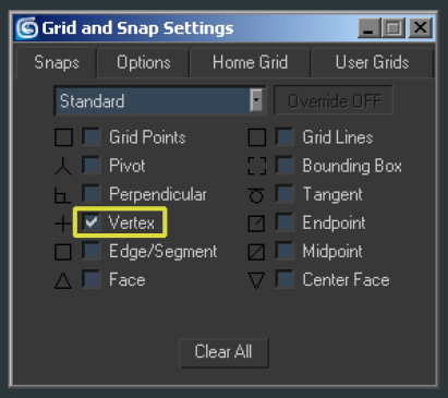
Snap Toggle Right-clicking the button will bring up the grid and snap settings where you can select what you want to snap to. When cutting, it’s sometimes good to have the snap to vertex option turned on. If you want to make a cut that isn’t snapped to a vertex, simply tap “s” again to turn snapping
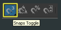
Hitting “s” or clicking the button shown here will turn on Snap Toggle.
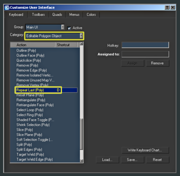
Repeat Last (Poly) I have this command assigned to the “d” key. By having this key assigned, it’s possible to repeat the same command multiple times. Be forewarned that it only works across the same subelement. If you use the connect tool on edges, and then switch to vertices, repeating last will not connect the verts. You must connect the first set of vertices, then each consecutive vertices you select can be connected by hitting your shortcut key. Locate it in the Main UI group, under the Editable Polygon Object category.
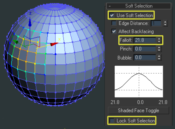
Soft Select When you need to move/scale/rotate existing geometry around in subtle ways, soft select allows you to move certain points directly and then have the surrounding points follow with a falloff value. Soft select is found in the edit-poly modifier panel. It can be used in any sub-object mode. The important settings:
Use Soft Select Turns the feature on and off.
Falloff This value is the distance the falloff travels away from the selection.
Lock Soft Selection Keeps all sub-objects at their current falloff value even after you’ve adjusted them. Normally upon changing, the falloff readjusts to the new placement based on the falloff value. Ticking the Lock box keeps these values so you can make multiple adjustments on the same sub-objects. These stay locked until the box is unticked.
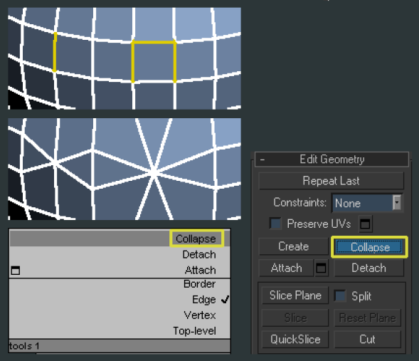
Collapse Used when merging multiple sub-objects together to an averaged position. Sub-objects must be consecutive, or they will collapse to each chunk of consecutive sub-objects center.
Collapse is found in the edit poly modifier panel, or the upper left tool box in the right click menu
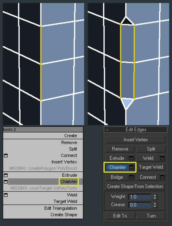
Chamfer When you want one edge to become two, in an averaged position of that edge, use chamfer. It rounds out the surface. Very useful for high poly inorganic parts, or for increasing the poly count of an area while keeping roughly the same shape. Can create triangles, so be aware you’ll most likely have to clean them up afterwards.

Chamfer is found in the edit poly modifier panel, or the lower left tool box in the right click menu.
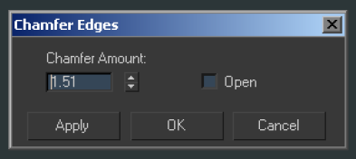
If you bring up the chamfer dialogue box (the small square to the side of the word chamfer) you can chamfer by a value. If you click and hold over the arrows, you can drag the cursor up and down to change the value.
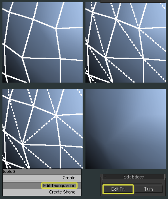
Edit Triangulation Every quadrangle has a triangle running through the middle of it. Depending on which way it divides the quadrangle, it will smooth differently and affect the silhouette (see below for example of the edge from the side before and after turning). The Edit Triangle command allows you to redraw which way the invisible edge divides the quad. You must first click upon one vertex you want it to connect to, and then the second. This will change the dotted line to now go in the new path you have drawn. Notice the change in the smoothing.
Editing triangles is for both a rounder shape, and better smoothing. Every model should include a pass of looking for edges to “turn”. Mostly I turn them as I model which I find to be more efficient.
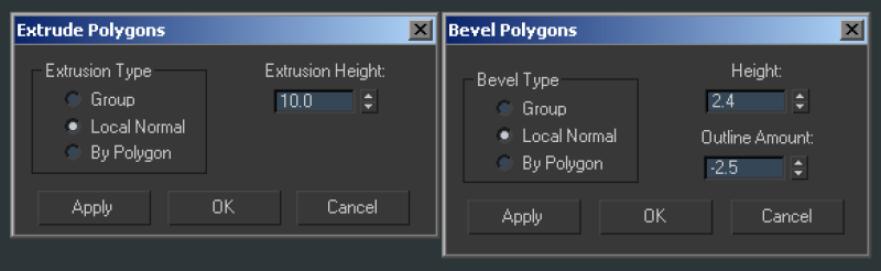
Extrude/Bevel Extrude and Bevel are two similar tools. Extrude offers the option of taking the selected faces or edges and pushing them outward, creating new geometry for the sides. Extrude offers you only distance outwards, while bevel adds the option to outline (make smaller or larger based on the surface area) Be sure to click the square option box to either side of the commands to get the numerical input window. The input window also offers the option of type, either group (the averaged normal off all selected sub-objects), local normal (each sub-object travels along it’s own normal while staying joined with the group), or by polygon (each sub-object travels along it’s own normal and stays separate from the other sub-objects.
Extrude and Collapse are found in the edit poly modifier panel, or the upper left tool box in the right click menu.
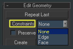
Constraints These are options to limit how your sub-objects can move. Edge only lets them be transformed along the edges they exist on, Faces only let them be transformed along the faces they exist on.
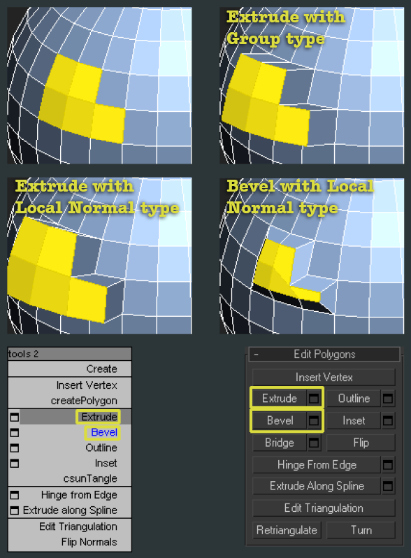
Other Commands Can be seen in the image next to this text.
csPolyTools is available from http://www.scriptspot.com. I use csUntangle to turn any poly into a perfect Ngon.
Remove Hitting backspace will remove the selected sub-object without destroying the geometry around it. It functions as a remove command rather than delete.